
Microsert(Heat Staking Inserts)
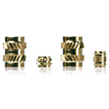 Knurling in alternate directions provides high tensile and torque strengths.
The symmetric design without orientation increases productivity and is advantageous for automatic machinery.
| Major Insertion Methods | Heat Staking Insertion, Ultrasonic Insertion, High Frequency Insertion |
| Material | Brass (C3604), Aluminum Alloy (made-to-order), Stainless steel (made-to-order) |
| Plastic | Thermoplastics |
■ Features
・ Non-orientation design for higher productivity
・ Knurling in alternate directions provides high strength
・ Suitable for use in automatic feeders and parts feeders
・ Full compliance with RoHS Directive
・ Knurling in alternate directions provides high strength
・ Suitable for use in automatic feeders and parts feeders
・ Full compliance with RoHS Directive
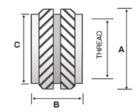
■ Dimensions
| Dimensional Drawing |
|
| Part Number | Thread and Pitch | A | B | C | Pilot Hole Dimension on Plastic (Reference) | |
| MS2.5-M1.6-3.0 | M1.6×0.35 | 2.50 | 3.00 | 2.10 | φ2.2 | ※ |
| MS2.9-M2-2.0 | M2×0.4 | 2.90 | 2.00 | 2.40 | φ2.6 | ※ |
| MS3.5-M2-3.9 | M2×0.4 | 3.50 | 3.90 | 3.10 | φ3.2 | |
| MS4.4-M2.5-5.7 | M2.5×0.45 | 4.40 | 5.70 | 3.80 | φ4.0 | ※ |
| MS4.6-M3-5.7 | M3×0.5 | 4.60 | 5.70 | 3.90 | φ4.0 | ※ |
| MS6.3-M4-8.1 | M4×0.7 | 6.30 | 8.10 | 5.54 | φ5.6 | ※ |
※Standard Parts ・ Unit:mm
■ Microsert Performance Data (Reference)
| Part Number | ABS | MC Nylon | PP | |||
| Pull-out(N) | Torque-out(N・m) | Pull-out (N) | Torque-out(N・m) | Pull-out(N) | Torque-out(N・m) | |
| MS2.5-M1.6-3.0 | 368 | 0.56 | 354 | 0.58 | 181 | 0.55 |
| MS2.9-M2-2.0 | 261 | 0.41 | 289 | 0.48 | 151 | 0.27 |
| MS4.4-M2.5-5.7 | 1,133 | 2.48 | 1,134 | 1.86 | 625 | 1.36 |
| MS4.6-M3-5.7 | 1,666 | 2.92 | 1,424 | 2.47 | 995 | 2.31 |
| MS6.3-M4-8.1 | 2,399 | 5.10 | 3,045 | 6.00 | 1,601 | 4.24 |
| Part Number | POM | Acryl | PVC | |||
| Pull-out(N) | Torque-out(N・m) | Pull-out (N) | Torque-out(N・m) | Pull-out (N) | Torque-out(N・m) | |
| MS2.5-M1.6-3.0 | 344 | 0.58 | 427 | 0.57 | 359 | 0.58 |
| MS2.9-M2-2.0 | 248 | 0.51 | 418 | 0.76 | 257 | 0.71 |
| MS4.4-M2.5-5.7 | 1,255 | 2.43 | 1,563 | 2.98 | 1,598 | 2.98 |
| MS4.6-M3-5.7 | 1,769 | 2.96 | 3,155 | 3.92 | 1,876 | 3.09 |
| MS6.3-M4-8.1 | 3,147 | 5.42 | 5,519 | 6.67 | 3,282 | 6.50 |
※The data above are experimental results obtained by Micro Fasteners. They are not a guarantee of the strength of our products.
1N≒0.098kgf 1N-m≒9.8kgf-cm
1N≒0.098kgf 1N-m≒9.8kgf-cm
■ NOTE
・The MS2.5-M1.6-3.0 has a different shape than the illustration above.
・ Headed inserts are also available.
・ Please contact us if you need Pb-free material for environmental reasons.
・ Pilot hole diameters are for reference only.
The diameter should be determined by tests before use.
・ Please contact us about the knurling design when knife locks are used for
polycarbonate (PC) and other materials which are sensitive to residual stress.
・ The diameter of the pilot hole for the mounting object should be smaller
than the outer diameter of the insert (Dimension C).
・ When inserts are tightened by screws, choose the screw length
so that screws do not reach the bottom of insert pilot holes.
・ The specifications are subject to change without notice.
・ Please contact us if you have any other questions.